![]()
![]()
![]()
![]()
![]()
![]()
![]()
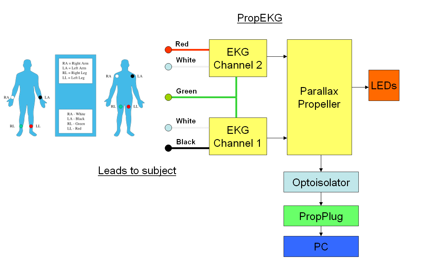
A Simple Heart Rhythm Monitor Utilizing the Parallax Propeller Microcontroller
Warning!
Risk of Electrical Shock!
Use the info provided here at your own risk!
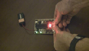
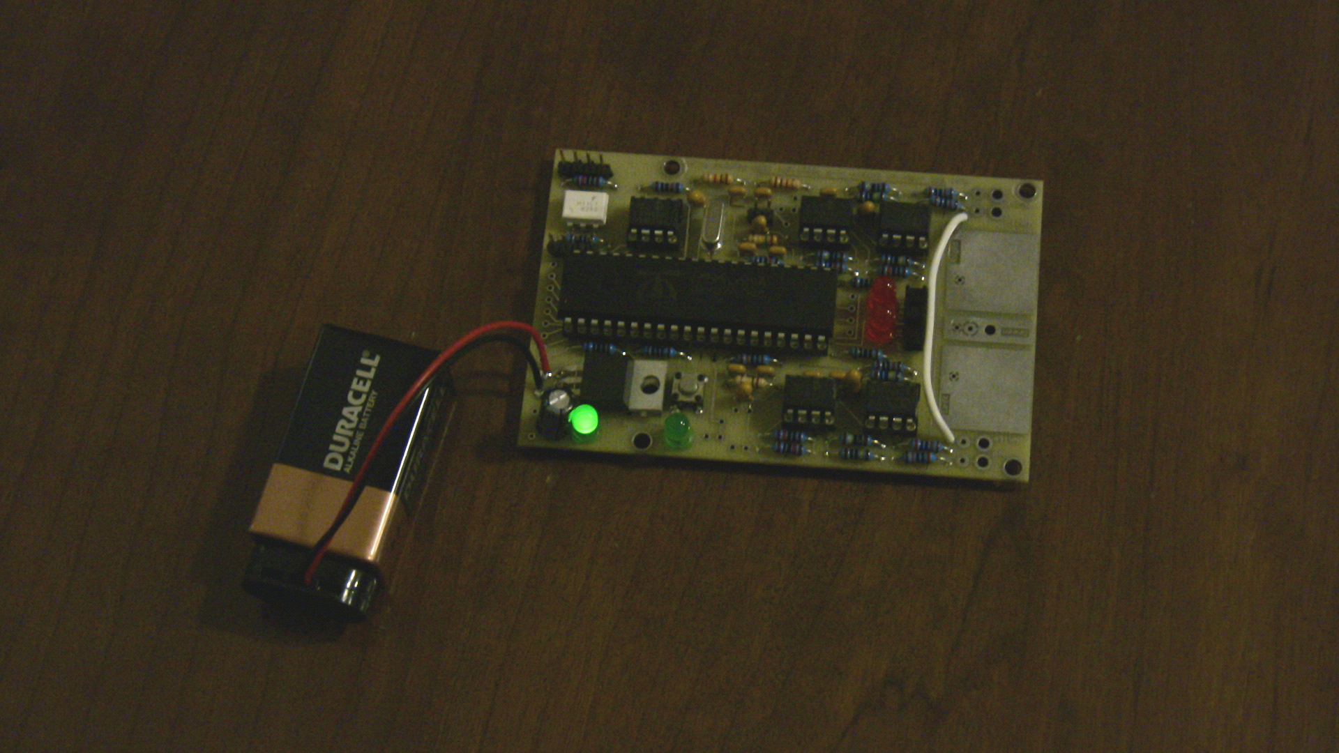
Using the thumbpads to detect heartbeat with flashing LED:
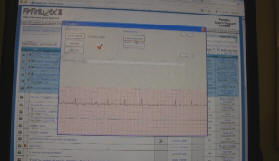
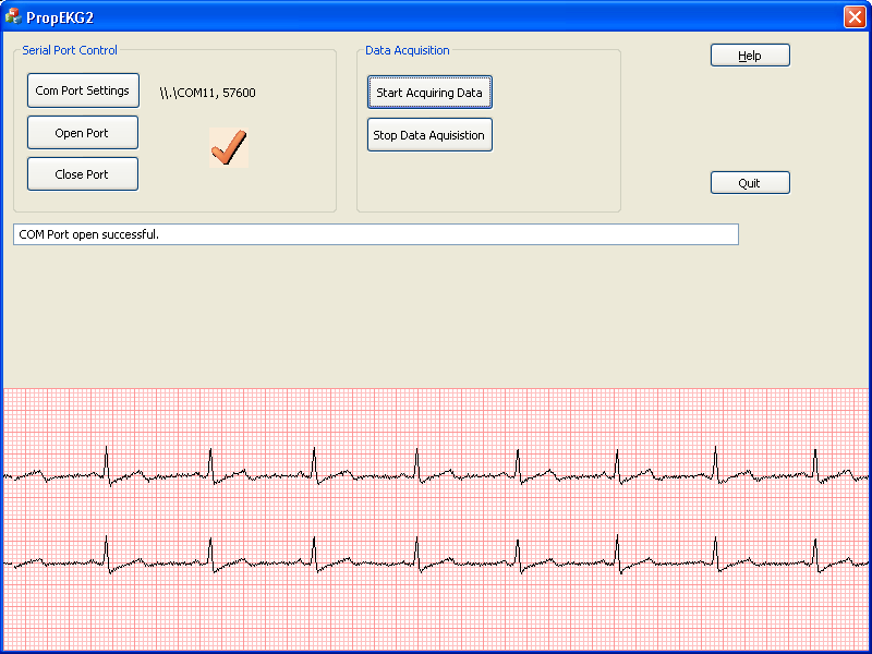
Using the optoisolated serial link with Windows to graph thumbpad EKG data:
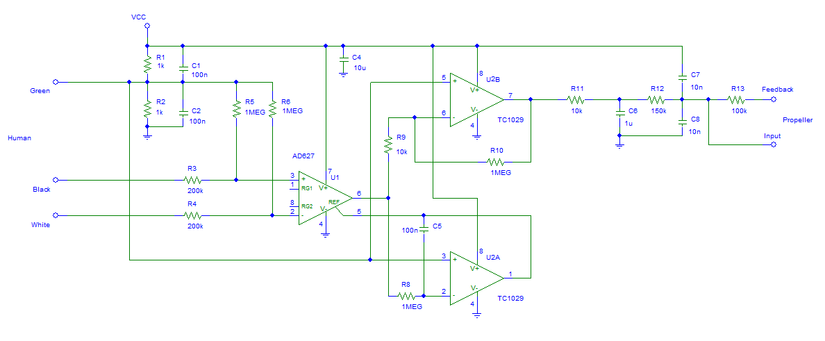
Schematic diagram of one channel of the EKG circuit.
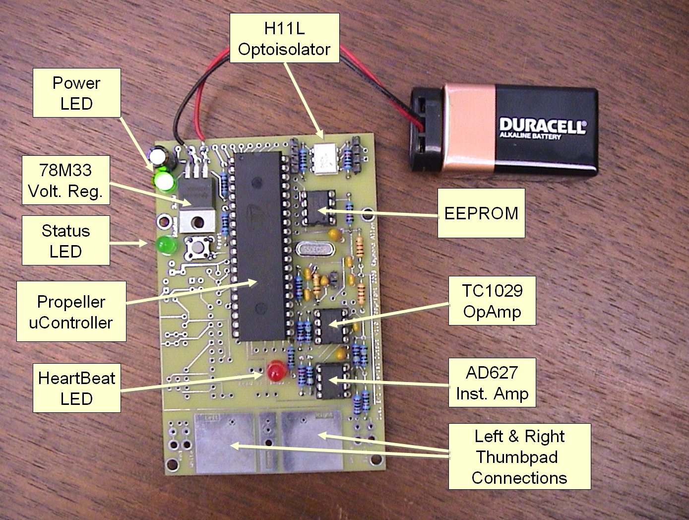
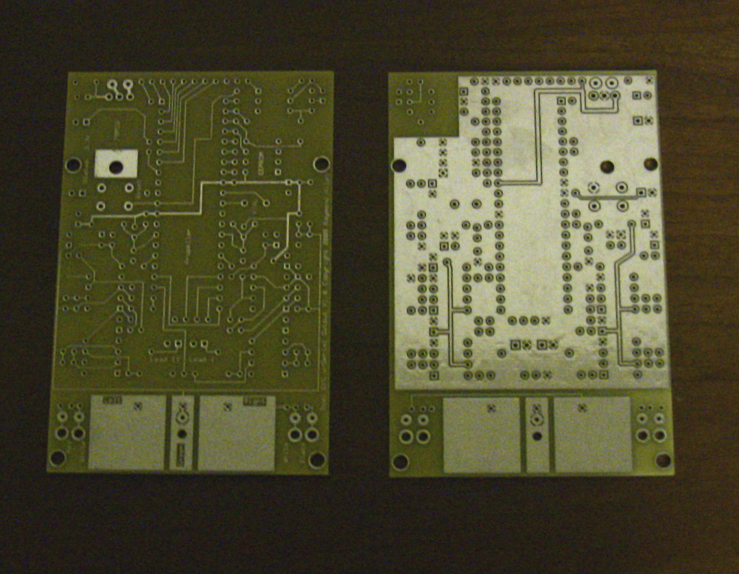
A complete circuit diagram of one channel of the analog EKG circuit is shown in figure above.. The circuit board has provisions for two identical channels, although only one is required for basic operation. The only active components are two 8-pin DIP amplifiers, the AD627 instrument amplifier (U1) and the TC1029 dual OPAMP (U2A and U2B).
An analog ground at Vcc/2 is formed by the resistor divider of R1 and R2. C1 and C2 are used to filter high frequency transients from this analog ground. In the usual case, the body is connected to this ground using the green wire (but, this grounding is not always necessary when operated from battery power).
The AD627 instrument amplifier amplifies the very small EKG voltage coming in through the black and white wires, through R3 and R4. R5 and R6 pull down these inputs to analog ground and reduce noise and allow single channel operation without the green wire. The AD627 has the impressive ability to amplify the EKG signal above the noise floor even with a large amount of common mode noise on the inputs. With pins 1 and 8 not connected, the AD627 has the default of 5X, which gives the maximum common-mode rejection
U2A, one of the two opamps of the TC1029 chip, is configured as an error integrator with R8 and C5. It’s function is to gently force the output level of the AD627 to be close to the analog ground (Vcc/2). This is done by integrating the difference between the output of the AD627 and analog ground and feeding the result into the ground reference pin of the AD627. This is necessary because the 100X amplification of the AD627’s output performed by U2B, the second opamp of the TC1029, and the need to stay within the power supply rails. U2B is configured as a simple 100X inverting amplifier using R9 and R10 with analog ground as reference.
R11 and C6 form a low-pass filter on the output of U2B. This is fed to Propeller ADC (analog-to-digital conversion) circuit formed by R12, R13, C7 and C8.
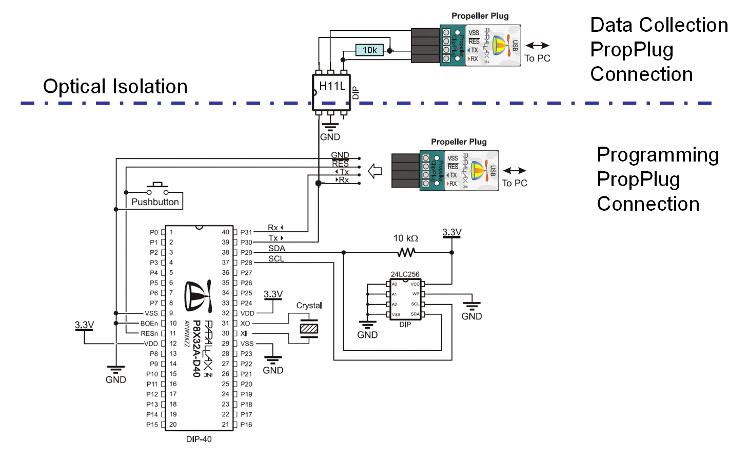
The remaining circuitry of the PropEKG is nearly identical to that used by the Propeller Education Kit, except for the addition of an optoisolated output to a computer. This modified circuit is shown in the figure below. An H11L optoisolator in 6-pin DIP package provides electrical isolation up to 7500 V. This provides a safer means of capture EKG data with a computer. The PropEKG Propeller firmware and Windows software are designed for this interface. It has been found to operate up to 57600 baud reliably. Note that this is a one-way connection. In fact, voltage from the TX pin of the PropPlug (which idles with an output of 3.3 Volts) is used to power the receive side of the H11L.
Modified basic Propeller circuit to allow optoisolated output to computer using a PropPlug.