![]()
![]()
![]()
![]()
![]()
![]()
![]()
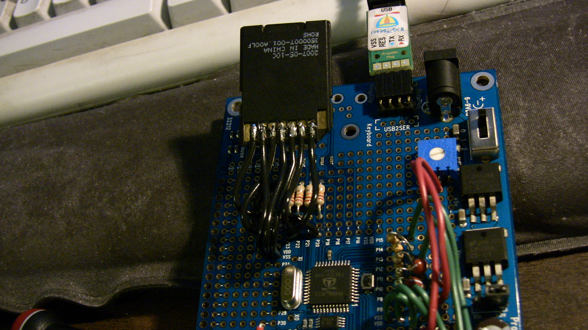 It is important to prewet both wires and SD card to minimize
melting!
It is important to prewet both wires and SD card to minimize
melting!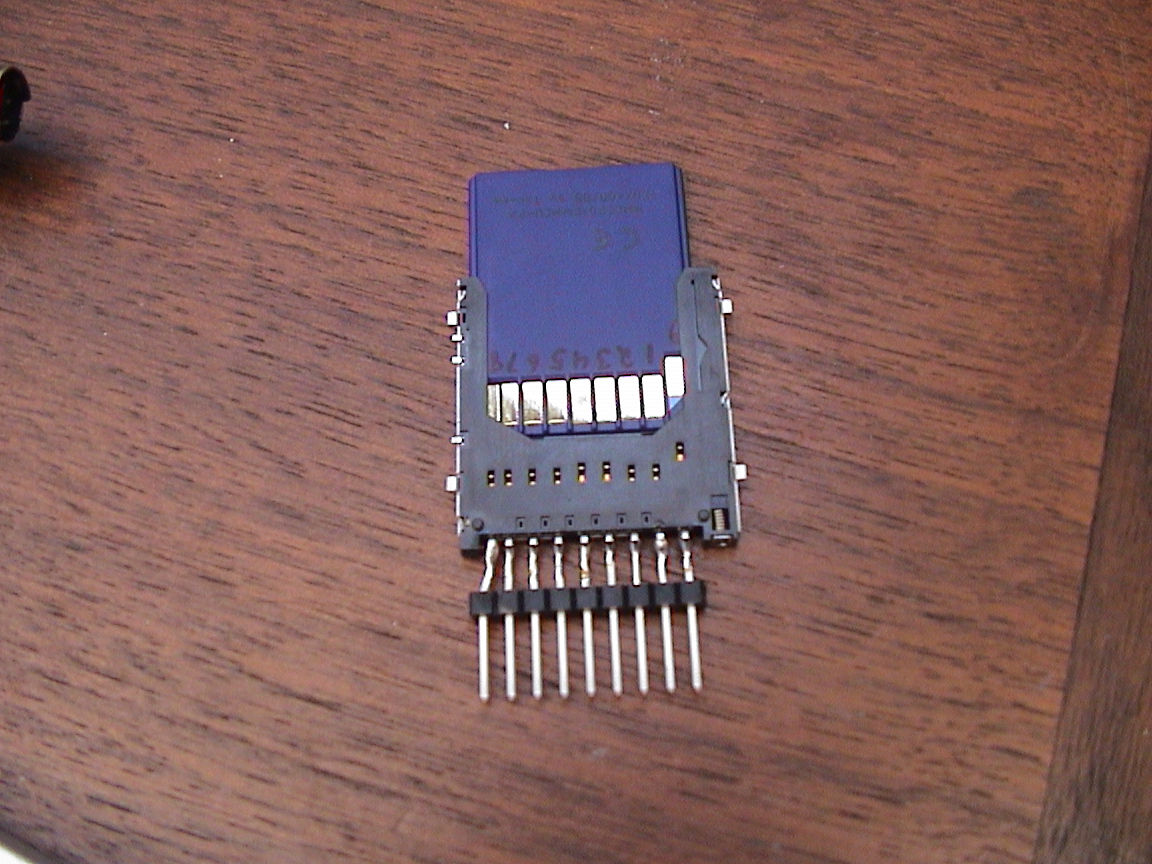
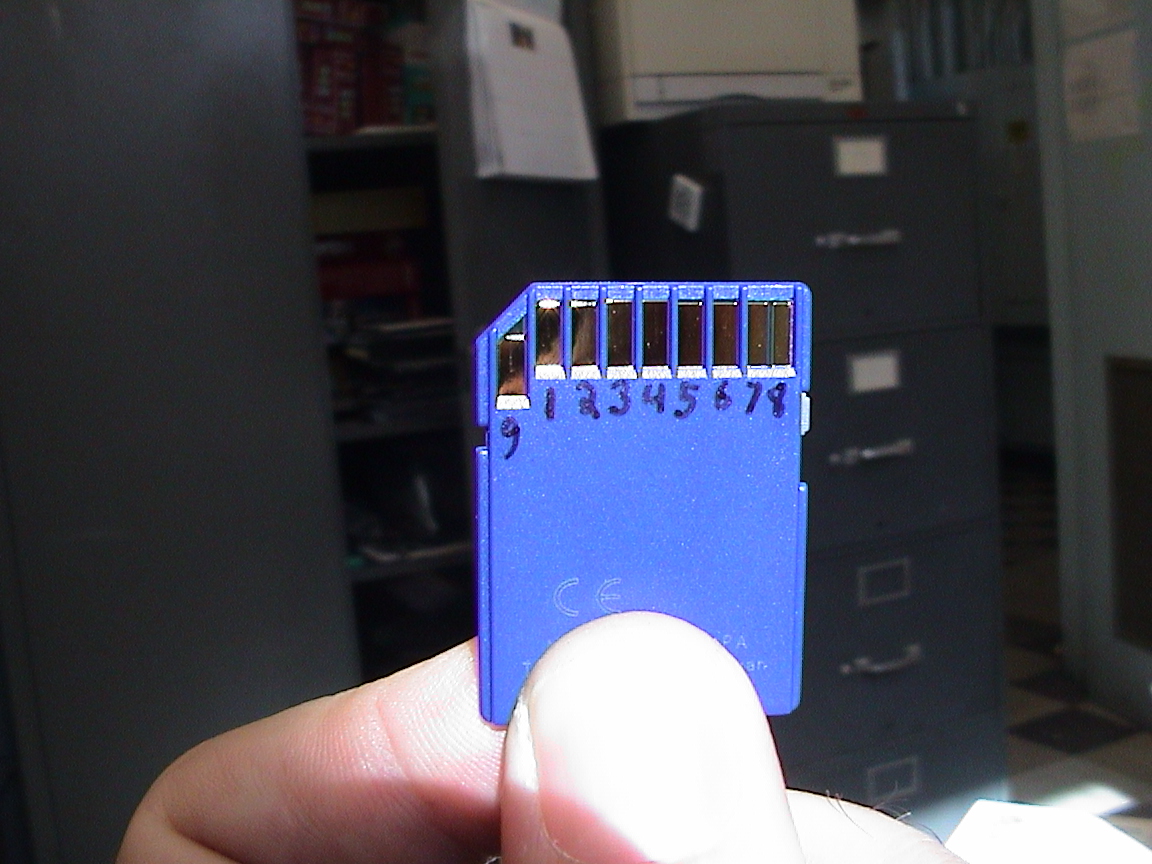 SD pin #s
| SD Pin | SPI Signal | Prop | Pull-Up Resistor |
| 1 (data line #3) | CS (chip select) | P3 | Yes |
| 2 (command line) | MOSI (Master Out/Slave In) | P2 | Yes |
| 3 (ground) | Vss | ||
| 4 (supply) | Vdd | ||
| 5 (clock) | SCK (clock) | P1 | Yes |
| 6 (ground) | Vss | ||
| 7 (data line #0) | MISO (Master In/Slave Out) | P0 | Yes |
| 8 (data line #1) | -- | Yes | |
| 9 (data line #2) | -- | Yes |
 (I used 18k resistors)
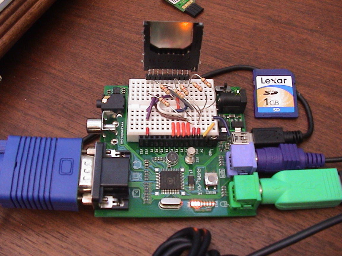
term: "tv_text" to
term: "vga_text"term.start(12) to
term.start(16) Card Size min max 4M 512 512 8M 512 1K 16M 512 2K 32M 512 4K 64M 1K 8K 128M 2K 16K 256M 4K 32K 512M 8K 32K 1G 16K 32K 2G 32K 32K